An Article Lets you Know Everything About Stepper Motors
Please click directly on any chapter you are interested in.
● What is a Stepper Motor?
A stepper motor is a brushless synchronous DC motor that converts digital pulses into rotation of a mechanical axis. Unlike many other standard types of motors, a stepper motor does not continuously spin for any number of revolutions until the DC voltage delivered to it is cut off. It has several coils that are organized in groups, the so-called "phases". If each phase is switched on in turn, the motor rotates step by step.
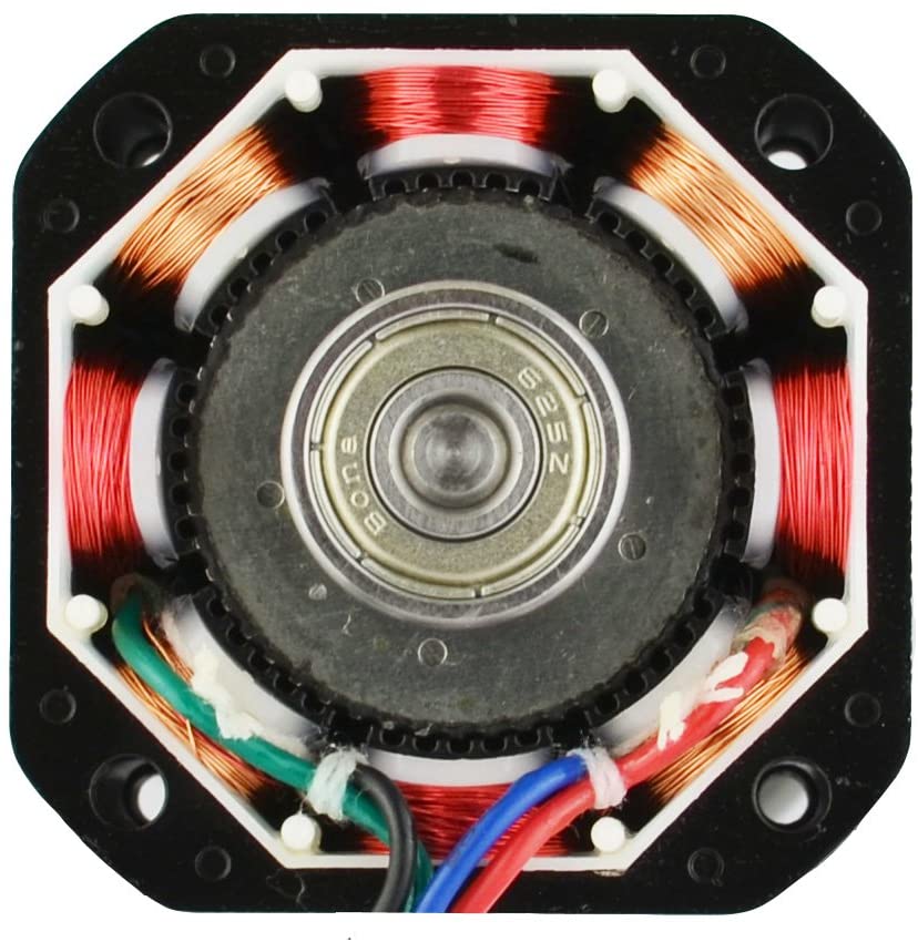
Stepper motors divide the entire rotary movement into several equal steps. As long as the motor is appropriately sized for the torque and speed of the application, the position of the motor can be controlled to move in one of these steps and remain there without any feedback from a position sensor.
Besides, a stepper motor is a digital input and output device. It is particularly suitable for applications in which the control signal is in the form of digital pulses and not in the form of analog voltages. A digital pulse sent to a stepper motor driver causes the motor to increase a certain angle of movement. As the frequency of the digital pulses increases, the stepping movement becomes a continuous rotation.
With computer-controlled stepping, you can achieve very precise positioning and/or speed control. As a result, stepper motors have become the motor of choice for many precision motion control applications.
● How Does Stepper Motor Work?
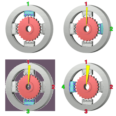
When current flows through the stator winding, the stator winding generates a vector magnetic field. This magnetic field will drive the rotor to rotate at a certain angle so that the direction of the rotor magnetic field is consistent with the direction of the stator magnetic field. When the vector magnetic field of the stator rotates through an angle. The rotor also rotates at an angle to this magnetic field. Each time an electrical pulse is input, the motor rotates an angle and moves forward one step. Its output angular displacement is proportional to the number of input pulses, and its rotation speed is proportional to the pulse frequency. Change the order in which the windings are energized and the motor will reverse direction. Therefore, the rotation of the stepper motor can be controlled by controlling the pulse number, frequency and energization sequence of each phase winding of the motor.
Common types of motors have iron cores and winding coils inside. The winding has resistance and will cause losses when electricity is applied. The magnitude of the loss is proportional to the resistance and the square of the current. This is what we often call copper loss. If the current is not a standard DC or sine wave, harmonic loss will also occur; the iron core will have hysteresis. The eddy current effect also produces losses in the alternating magnetic field, and its size is related to the material, current, frequency, and voltage. This is called iron loss.
Both copper and iron losses appear in the form of heat, affecting the efficiency of the motor. Stepper motors generally pursue positioning accuracy and torque output, and their efficiency is relatively low. The current is generally larger and has higher harmonic content. The frequency of current alternation also changes with the change of rotation speed. Therefore, it is common for stepper motors to heat up, more so than normal.
The motor converts electrical energy into mechanical energy, and the stepper motor is an open-loop control element that converts electrical pulse signals into angular displacement or linear displacement. Under non-overload conditions, the motor's speed and stop position only depend on the frequency and number of pulses of the pulse signal and are not affected by load changes. In other words, if a pulse signal is added to the motor, the motor will rotate by a step angle. The existence of this linear relationship, coupled with the characteristics of the stepper motor that only has periodic errors and no accumulated errors. It makes it very simple to use stepper motors to control speed, position and other control areas.
● Stepper Motor Size
Stepper motors are classified by frame size, such as "Nema 17" or "Nema 23". Ever wonder how this happens or what it means? The American Electrical Manufacturers Association sets standards for many electrical products, including stepper motors. Generally speaking, "Nema 17" means the motor's mounting surface is 1.7inches square. Therefore, the dimensions of the Nema 23 stepper motor are 2.3inches square. Or 57mm as shown below.
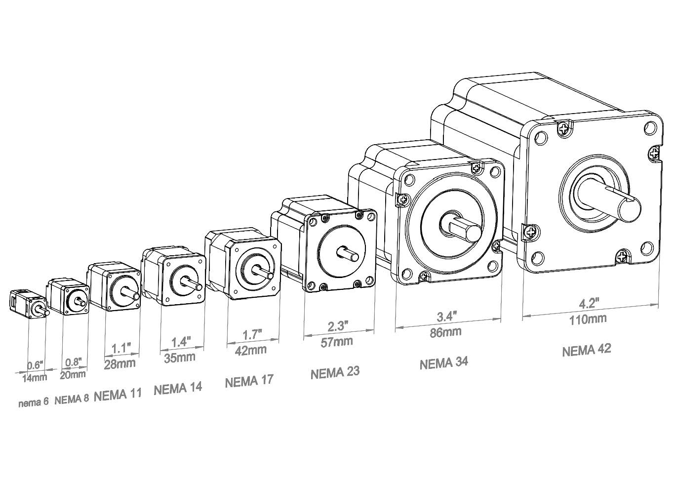
The photo below includes Nema size 06, 08, 11, 14, 17, 23, 24, 34, and 42 stepper motors. Size 24 is a bit of an anomaly - there is no official Nema definition for size 24. It mounts similarly to size 23, but is slightly wider (approx. 4mm), allowing the use of larger rotors and stators and therefore approximately 30% more torque.

Essentially, manufacturers agree on the proposed standard. This gives manufacturers greater design flexibility because they know in advance that one Nema 17 motor will fit another Nema 17 mount without having to redesign anything; especially if they choose to change motor suppliers.
● Stepper Motor Types
There are many types of stepper motors sold by STEPPERONLINE, and understanding the characteristics and uses of different types of stepper motors will help you decide which type is best for you.
Hybrid stepper motor is a combination of variable reluctance and permanent magnet motor. The stator is electromagnetically stimulated like variable reluctance stepper motor, and the rotor of the stepper motor is axially magnetized like permanent magnet stepper motor. This stepper motor is an actuator that converts electrical pulses into angular displacement.
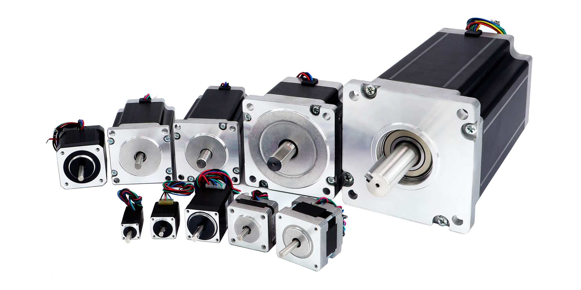
Compared to the other two types of stepper motors, hybrid stepper motors provide higher torque with smaller step angle and have a better dynamic property. With the development of science and technology, especially the development of permanent magnet materials, semiconductor technology and computer technology, these stepper motors have been widely used in industrial automation, robotics, textile and medical industries.
A closed-loop stepper motor is a stepper motor with an encoder added at the end of the motor to achieve closed-loop control. The closed-loop control of a stepper motor is a servo system that uses position feedback and/or speed feedback to determine the phase change appropriate to the rotor position, which can greatly improve the performance of the stepper motor without losing steps.
The closed-loop stepper motor adopts a double-winding structure, and its motor uses a high-precision linear encoder. Every time the motor rotates one frame, the encoder will output a pulse, so that the accurate rotation position of the motor can be obtained, while ordinary stepper motors only have one The position of winding and motor rotation is unreliable.
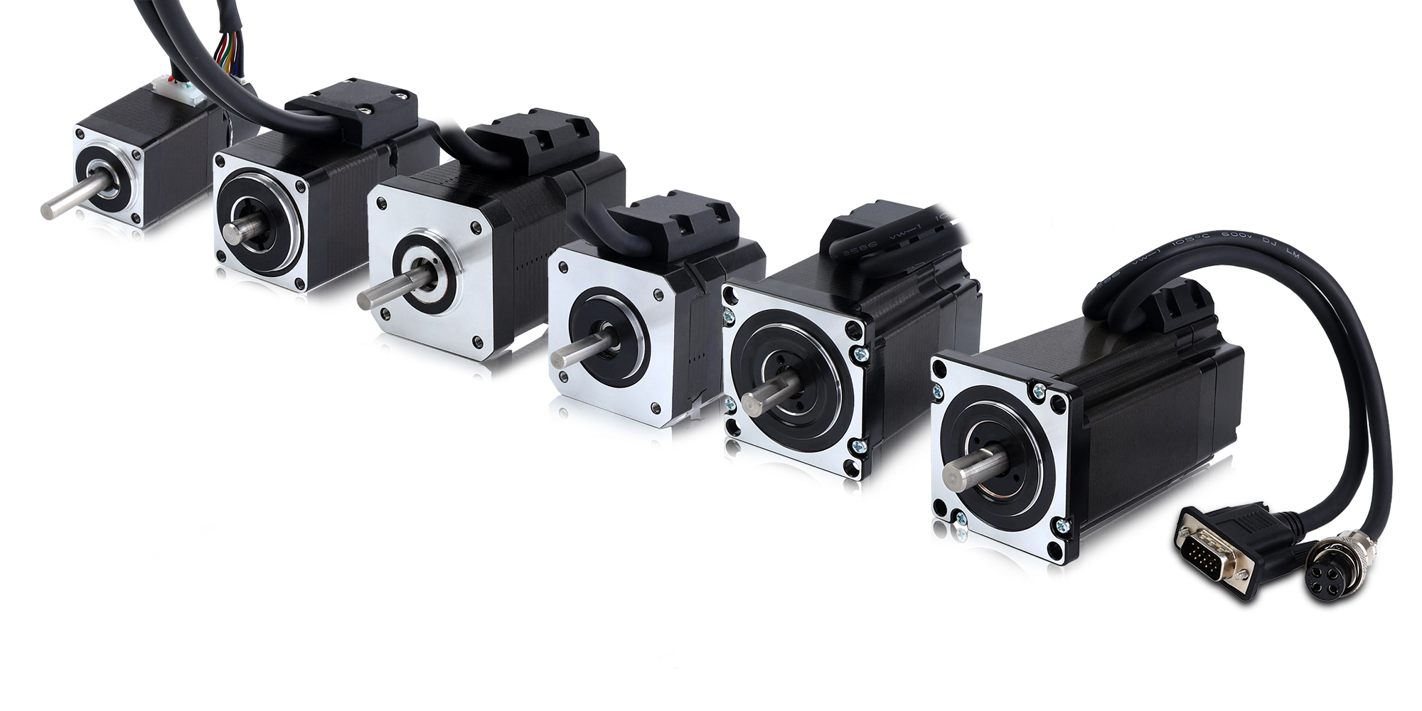
The closed-loop stepper motor adopts latch control, which requires the input of a reference pulse. Through feedback control, the control pulse can be synchronized. The rotation position of the motor can be maintained constant, while the ordinary stepper motor adopts open-loop control and does not need to input a reference pulse. Only the step frequency and direction of the motor need to be controlled, and the rotation position of the motor is uncontrollable.
Compared with ordinary stepper motors, closed-loop stepper motors have higher dynamic response capabilities and can achieve precise rotational position control with small position errors. Moreover, it has high precision, and the position accuracy can be controlled within 0.1degrees, while the position accuracy of ordinary stepper motors can only be controlled within 1degree, with poor operating stability and large position errors.
In addition, closed-loop stepper motors have a higher load capacity and can withstand larger loads, while ordinary stepper motors have a lower load capacity and have poorer endurance.
Integrated stepper motors combine stepper drives and motors in a single unit. Integrated stepper motors offer a space-saving design that reduces wiring and saves costs compared to separate motor and drive components. They are ideal for applications such as packaging and labeling, automated test and measurement, automated assembly and life sciences.
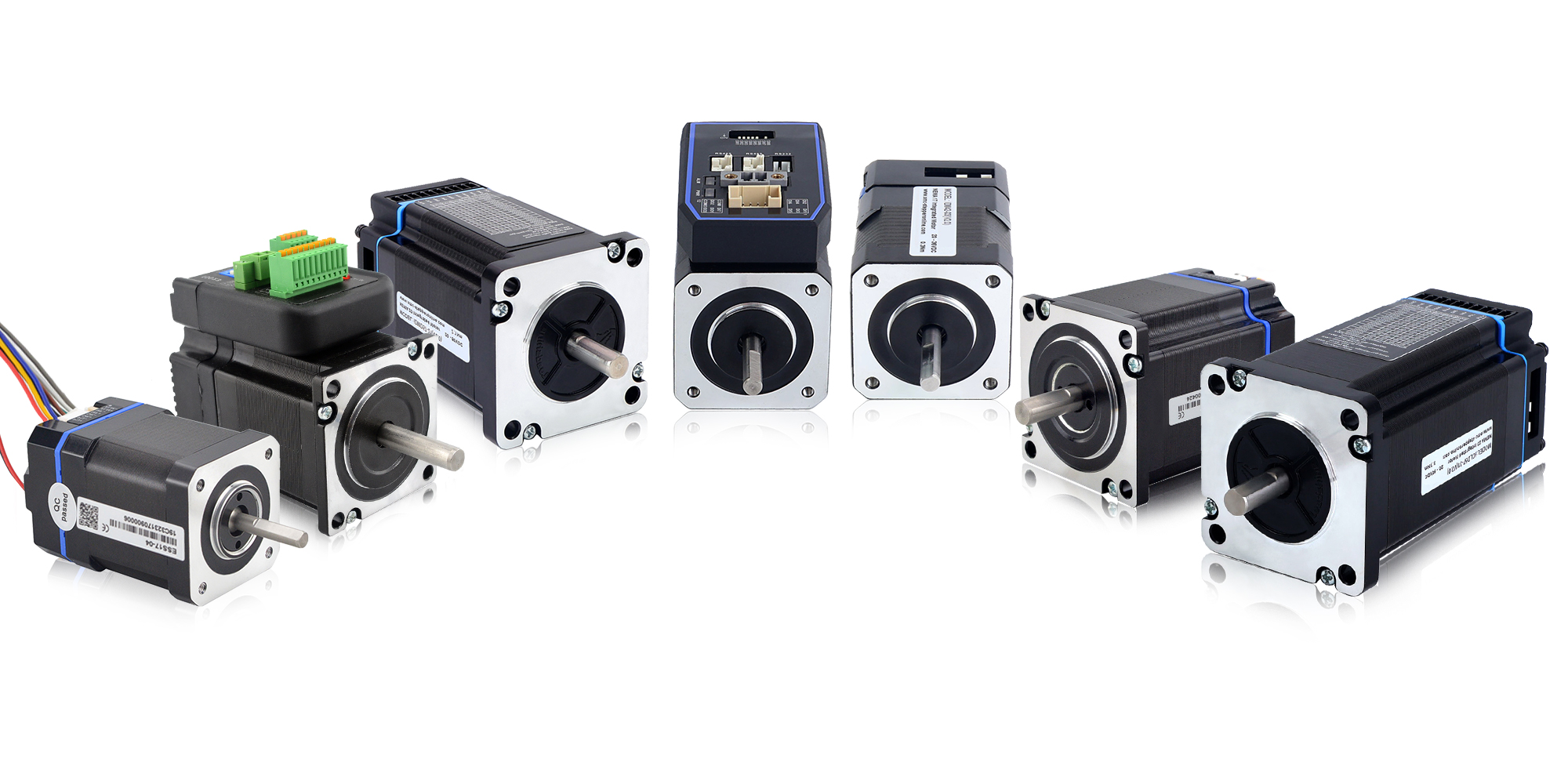
Other benefits of integrating motors and drive units include ease of implementation, reduced wiring complexity, faster system setup and design, and guaranteed motor-drive compatibility.
● Permanent Magnet Stepper Motor
Permanent magnet motors use a permanent magnet (PM) in the rotor and work with the attraction or repulsion between the rotor magnet and the stator electromagnets. The rotor of permanent magnet stepper motor is made of permanent magnet steel. The stator of the stepper motor is processed into a claw-shaped tooth pole by stamping method, and the rotor adopts a permanent magnet magnetic steel with radial multi-pole magnetization. The magnetic field generated by the direction of the coil current is mutually exclusive with the rotor magnetic field, so that the motor rotates reversely.
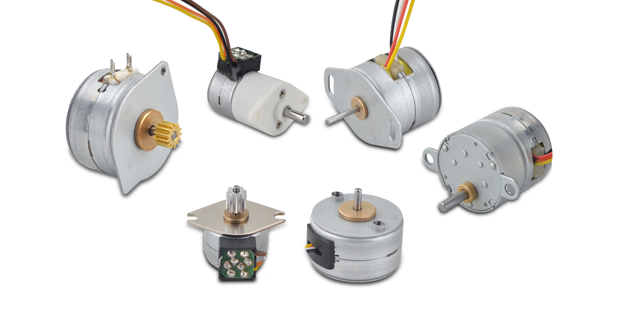
This stepper motor is also known as pm stepper motor, the axial direction of the whole motor stator and rotor is divided into two sections, and the middle is separated by a magnetic separation piece. The two sections are mutually separated by a step angle, and each consists of a stator, a rotor and a ring winding which is sleeved on the stator. The pm stepper motor is mainly used in computer peripheral equipment, photographic systems, optoelectronic combination devices, valve control, nuclear reactors, bank terminals, CNC machine tools, automatic winding machines, electronic watches and medical equipment, etc.
● Variable Reluctance Stepper Motor
A variable reluctance stepper motor is a type of electric motor that works on the principle of magnetic reluctance. This motor is constructed with an iron rotor and several stator windings. The windings are magnetized in a specific sequence, causing the rotor to move in discrete steps.
Variable reluctance stepper motors provide high step rates and good torque at low speeds. However, at higher speeds the performance may be less satisfactory due to resonance issues.
Variable reluctance stepper motors are considered rugged and reliable, which makes them suitable for environments where the motor may be subject to harsh conditions.
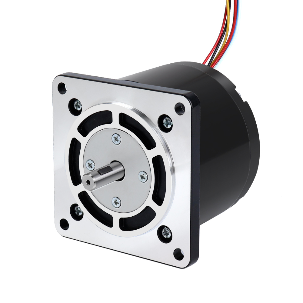
One of the main disadvantages of variable reluctance stepper motors is that they tend to be noisier than other types of stepper motors. This is because the rotor is poorly damped, resulting in higher levels of mechanical vibration.
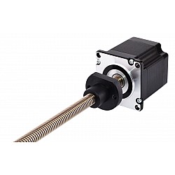
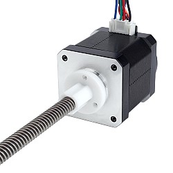
Linear stepper motors are a special type of stepper motor whose design and working principles are different from traditional rotary stepper motors. A linear stepper motor is a linear motor that achieves linear displacement through linear motion rather than the rotational motion achieved by traditional stepper motors. The structure of a linear stepper motor usually consists of a fixed stator and a movable slider. The stator is equipped with coils inside, and the slider is equipped with permanent magnets. When current passes through the stator coil, a magnetic field is generated. The interaction between the permanent magnet on the slider and the magnetic field of the stator generates an attraction or repulsion force, thereby causing the slider to move linearly on the fixed axis. Controlling a linear stepper motor is similar to a traditional stepper motor. By controlling the direction and magnitude of the current, the position and speed of the slider can be controlled. The pulse signal of each stepper motor moves the slider by a fixed step, so that precise linear displacement can be achieved.
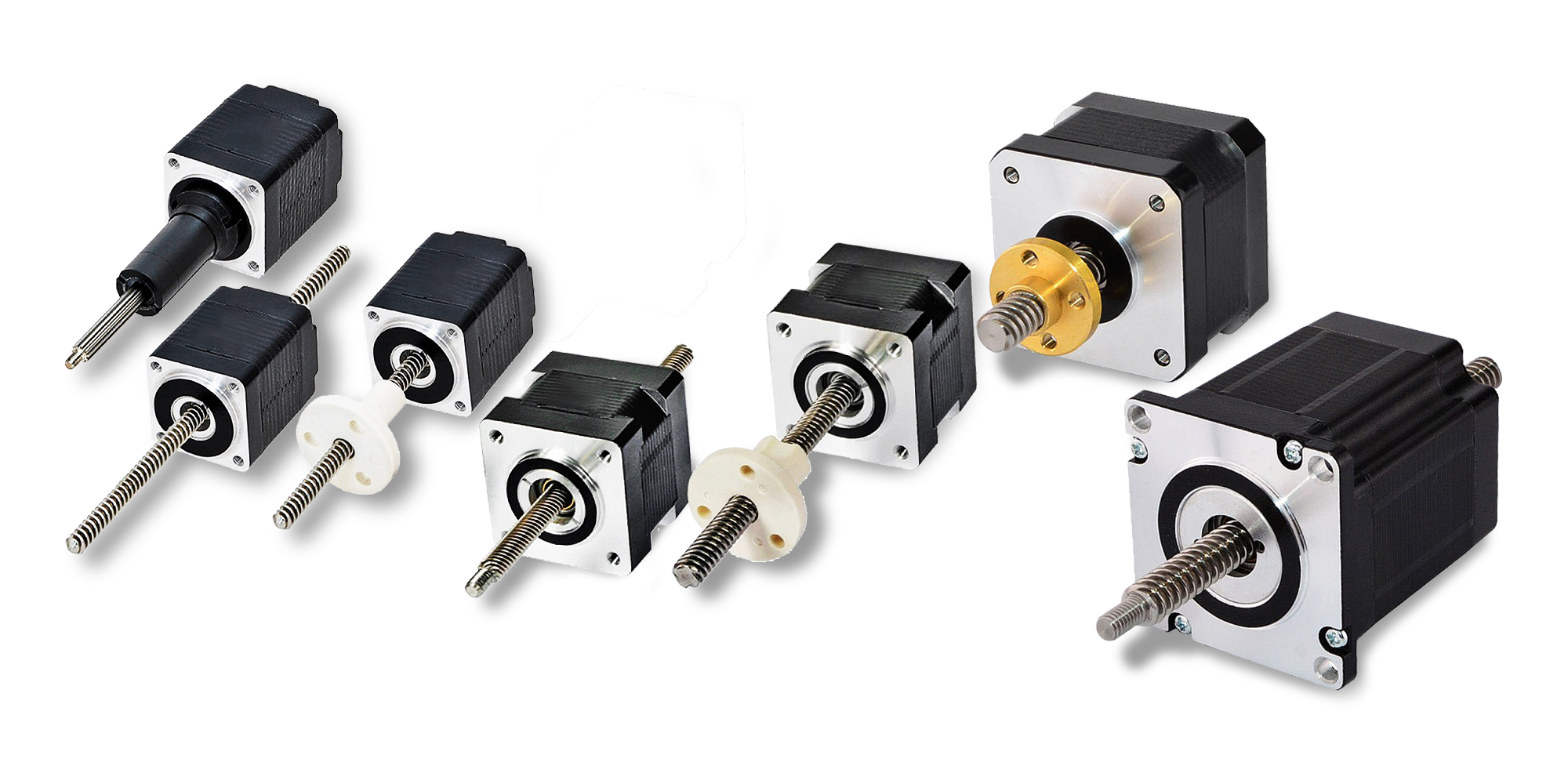
There are three common types of linear stepper motors, namely external drive, through-shaft and fixed-shaft. It can be selected according to the key indicators of specific applications. Linear stepper motors have the advantages of high precision, zero-backlash transmission, and fast response, so they are favored in applications that require high-performance linear motion control.
● Unipolar vs. Bipolar
A stepper motor is a motor that controls the angle of rotation through electrical pulses. Bipolar stepper motors and unipolar stepper motors are two common types of stepper motors. The main difference between them is the control method. A bipolar stepper motor needs to reverse current to change the direction of the rotor, so it requires 4 electrodes to control the direction, each electrode has two states (ON/OFF).
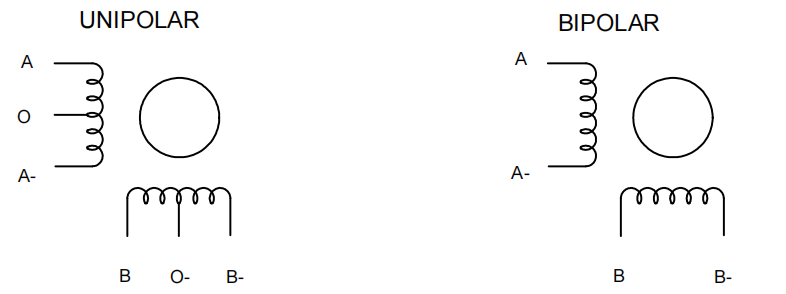
A unipolar stepper motor only needs two electrodes to control the rotation of the rotor, and the motor rotates by changing the direction of the current. Therefore, compared with bipolar stepper motors, unipolar stepper motors only need 2 electrodes to achieve the same motion control. However, since unipolar stepper motors require the addition of a unipolar driver in the control circuit, the circuit complexity is slightly higher.
Bipolar stepper motors and unipolar stepper motors each have their own advantages and disadvantages, and the appropriate motor can be selected according to the specific application scenario.
The advantages of bipolar stepper motors are large torque, fast speed, high precision, and simple control, so they are often used in situations where high-speed and high-precision control are required. The torque and precision of unipolar stepper motors are compared to those of bipolar stepper motors. The motor is worse and slower. In addition, the drivers used in unipolar stepper motors are costly and have fewer options.
● How to Choose Stepper Motor, Driver and Power Supply?
Stepper motors are a good choice when you need to control movement. They can be used in scenarios where control of rotation angle, speed, position and synchronization is required.
So, when we choose a stepper motor, there are several factors that need to be taken into consideration.
1. How is the motor coupled to the load?
After determining the type of coupling between the motor and the load, you can select a stepper motor based on shaft length, diameter, and shaft type. Currently, STEPPERONLINE standard stepper motors have a variety of shaft lengths, shaft diameters and shaft types, and can provide various customized services for the motor shaft.2. How fast does the load need to move or accelerate?
When choosing the right motor, you need to consider the balance between speed and load. For some equipment that requires fast movement, we can choose high-speed motors, but if the load is larger, we need to choose a motor with greater torque. Therefore, when selecting a motor, you must consider the balance between speed and load according to actual needs, and choose a motor that can satisfy both the movement speed and the load. The following is the maximum speed and recommended speed of each size motor under no load condition.
| No Load Speed | |||
| Motor Type | Dimensions(mm) | Max. Speed(rpm) | Recommended Working Speed(rpm) |
| Open Loop Motor | Nema 6(14x14) | 1000 | 100-600 |
| Nema 8(20x20) | 1000 | 100-600 | |
| Nema 11(28x28) | 1000 | 100-600 | |
| Nema 14(35x35) | 1000 | 100-600 | |
| Nema 16(40x40) | 1000 | 100-500 | |
| Nema 17(42x42) | 1000 | 100-500 | |
| Nema 23(57x57) | 1000 | 100-500 | |
| Nema 24(60x60) | 1000 | 100-500 | |
| Nema 34(86x86) | 1000 | 100-400 | |
| Nema 42(110x110) | 500 | 100-300 | |
| Closed Loop Motor | Nema 8(20x20) | 2000 | 100-1500 |
| Nema 11(28x28) | 2000 | 100-1500 | |
| Nema 14(35x35) | 2000 | 100-1000 | |
| Nema 17(42x42) | 2000 | 100-1000 | |
| Nema 23(57x57) | 1500 | 100-1000 | |
| Nema 24(60x60) | 1500 | 100-1000 | |
| Nema 34(86x86) | 1500 | 100-1000 | |
You can also determine whether the motor meets your load speed requirements based on the motor curve diagram.
3. How much torque is required to move the load?
Most motors have torque ratings. This is what you need to look at to decide if the motor has the strength to do what you want. The holding torque of a stepper motor is similar to the "power" of a conventional motor. However, the physical structure of stepper motors is completely different from AC and DC motors, and the output power of the motor varies depending on the speed, current and input voltage.
Generally speaking, if the required torque is less than 0.8N.m, choose Nema 8 (20x20mm), Nema 11 (28x28mm), Nema 14 (35x35mm), Nema 16 (39x39mm), Nema 17 (42x42mm); if the torque is about 1N.m, choose a Nema 23 stepper motor. If the torque is more than several N.m, you must choose a stepper motor with specifications such as Nema 34 and Nema 42.
4. What accuracy is required when positioning a load?
The accuracy of stepper motors increases when the steps are smaller. This is because one revolution is divided into more careful, more numerous steps that leave less room for error. A stepper motor with an angle of 0.9°, for example, delivers a higher accuracy than a stepper motor with an angle of 1.8°.
A common misconception is that 1.8° motors running at half steps will achieve the same accuracy as 0.9° stepper motors running at full steps. Another misconception is that torque is lost when using a 0.9° stepper motor. These assumptions are incorrect, and an understanding of the mechanical design features can explain why.
In general, 0.9° stepper motors are best suited for high speed and high precision applications. Conversely, 1.8° stepper motors deliver higher torque but lower accuracy. Also available are 0.9° stepper motors with a patented 12-pole design. These more advanced motors combine the features of 0.9°and 1.8° motors and offer high accuracy and higher torque.
To get the most out of your stepper motor, you need to use the appropriate driver. When selecting a driver, there are three key elements to keep in mind: voltage, current, microstepping and number of phases . Each plays an important role in the performance of the motor. Failure to consider these parameters can result in poor performance, louder noise, or even motor overheating and failure, resulting in lost production time and increased maintenance costs.
1. Rated voltage
Exceeding the maximum rated voltage of the motor or operating it with a higher supply voltage can cause the motor to malfunction. For this reason, you must know the maximum rated voltage or the typical rated voltage of the motor from the product description or the torque curve when selecting a stepper motor driver. Stepper motors are typically powered by drivers that operate on AC (120V or 240V) or low-voltage DC (such as 24V, 36V or 48V). If you run a motor at a higher voltage than specified, such as a motor rated for 24VDC, at a high voltage, the motor will quickly overheat. Conversely, a motor operated at too low a voltage (e.g. a high voltage motor running at 24VDC) will produce less power and may cause the motor to stall if the load is not reduced.
2. Current Rating
Make sure that the driver is suitable for a wide current range so that you can test the system at different voltages that are suitable for your application. For the current rating, you should consider both the continuous or effective current and the peak current requirement. In brushed and brushless DC motors, the back EMF is not present during start-up and standstill and the driver only sees the winding resistance of the motor. There is therefore a current surge before the motor spins up and generates a back EMF that is opposite to the supply voltage, which reduces the current consumption. Even if your application only requires a maximum of 1A continuous current during normal operation, it may have to process 2 to 3 times or even more continuous current when starting up and stalling.
3. Microstepping
Stepper motors move in steps that are normally 1.8°, i.e. 200 steps per revolution. This can be a problem if we need small movements. One option would be to use some kind of gearbox, but there is another option – microstepping. Microstepping means that we can have more than 200 steps per revolution and therefore smaller movements.
When operating stepper motors with full steps, the output of the stepper motor driver looks like a square wave signal and generates coarse movements. The larger the microsteps, the more the output signal looks like a sine wave and the stepper motor moves more smoothly. However, this also has a disadvantage. As the microstep value increases, the torque drops sharply, and if the value is too large, the motor can not generate enough torque to turn at all. Normally, 1/4, 1/8 or even 1/16 can be used to achieve satisfactorily smooth movements and still generate enough torque.
4. Number of phases
Stepper motor drivers are used to control a specific number of phases. For typical unipolar and bipolar stepper motors, two-phase drives are used, but variable reluctance motors use three-phase drives. Before selecting the driver, please confirm the phase number of the motor.
When using a stepper motor, you'll need a power supply to give power to stepper motor. A right power supply can make your stepper motor working at optimum performance, Instead, a wrong power supply might cause low performance or larger waste of energy.
Below are few tips for choosing power supply:
| Motor Size | Driving Voltage |
| Nema 8 - Nema 17 | 12 - 24VDC |
| Nema 23, Nema 24 | 24 - 48VDC |
| Nema 34 | 48 - 100VDC/30 - 70VAC |
| Nema 42 - Nema 52 | 110 - 220VAC |
- Confirm motor’s rated current. You can find it at motor datasheet.
- Confirm driving voltage. Driving voltage is main factor when choosing a power supply. Normally, higher voltage will have better performance.
Below table are the recommend voltage for stepper motors, you can choose a driving a right voltage as per your application.
Calculate the power value. We provide a simple formula for you:
P=n*I*V*1.2P: Power value
n: Number of stepper motors
I: Motor rated current
V: Driving voltage
1.2: meaning 20% of margin
eg. 3 units of motors with 3A rated current each and driving voltage is 36V, the estimate power is about: 3*3A*36V*1.2=388.8W. so, you can choose an 36V 400W power supplier
Please note: The formula is just an estimate value of power, different working condition will need different power. For example, in a 3 axis system, not all 3 motors working at same time, and not all 3 motors working with max load etc. At this condition, the power value might be lower than the value by which calculated by formula.
● Stepper Motors Advantages and Disadvantages
Advantages of Stepper Motors
- Due to their internal structure, stepper motors do not require sensors to detect the motor position. Since the motor moves in "steps", the motor position at a certain point in time can be determined by simply counting these steps.
- Stepper motors are also very easy to control. Although the motor requires a driver, it does not require complex calculations or settings to function properly. In general, the amount of work required for control is lower compared to other motors. With the microstepping method, you can achieve a high positioning accuracy of up to about 0.007°.
- Stepper motors offer great torque at lower speed, are excellent for holding position and have a long service life.
- The rotor of the stepper motor has a large mass and high inertia. It is prone to vibration and noise during high-speed operation, which affects the stability and accuracy of the movement. This is a major disadvantage of stepper motors and measures need to be taken to mitigate or eliminate this effect.
- The working principle of the stepper motor is to control the position and speed through short-term instantaneous pulse control. Long-term operation can easily cause the motor to heat up or even burn out. For applications that require continuous operation for long periods of time, stepper motors may not be the best choice.
Stepper Motor Uses and Applications
Due to the characteristics of stepper motors, they are used in many applications requiring simple position control and the ability to maintain position, including:
1. 3D Printers
Stepper motor is one of the important components of 3D printer. Depending on the type of printer, they can be used for a variety of applications. For example, stepper motors are used to individually move an extruder or build platform along the x, y, and z axes. Typically the extruder assembly is equipped with a stepper motor that pulls the filament into the extruder.
Stepper motors are unique in that they can move to a known interval and then stay in that position. Because they can repeatedly move objects to a fixed position, they are often used in robots and printers.
Stepper motors come in many sizes. The most commonly used sizes in 3D printers are NEMA 14, NEMA 17, NEMA 23, and NEMA 24.
2. CNC Machines
Stepper motors are an alternative choice to servo motors and can provide power for most types of CNC machinery. CNC applications encompass a wide range of manufacturing processes where pre-programmed computer software controls the operation and physical movement of machine tools in factory and manufacturing environments.While stepper motors in CNC applications are often seen as a more "economical" alternative to servo motors, this is an oversimplification based on outdated technological knowledge, and it is not always strictly accurate today. Stepper motors do tend to be cheaper than servo motors for the same power, but modern versions are equally versatile. As a result, stepper motors find more widespread applications and are present in a broader range of machines and systems, from machine tools to desktop computers and automobiles.
CNC stepper motors have a critical advantage over servo motors in that they do not require encoders. Servo motors are inherently more challenging to understand and operate than stepper motors, partially because they include encoders, which are more prone to failure than many other components in reliable servo motors. Stepper motors do not need encoders, theoretically making them more reliable than servo motors.
Additionally, stepper motors are also brushless (unlike servo motors), meaning they do not require regular replacement as long as the bearings are in good working condition.
3. Camera Lenses
Stepper motors are widely used in various applications within high-end camera technology. They can be employed to control extremely precise internal structures, such as automatic focusing and aperture settings within the lens. Additionally, stepper motors find applications in the housing and external mechanical structures of security cameras and remote monitoring systems.
In particular, stepper motors, along with electric camera sliders, enable very smooth operation of camera positioning devices. This means that lenses captured by safety devices can be reliably held, avoiding potential image distortion issues caused by the camera's physical movements around its field of view. Stepper motors provide several attractive features for camera and video surveillance positioning systems, including full torque when stationary, extremely precise and instantaneous response times for all motion inputs, consistent repeatability of pre-programmed movements, and simple open-loop control based on fixed step sizes.
In addition to the above, stepper motors are also used in security, service robots, printers, scanners, textile machinery, packaging machinery, compact disc drives and intelligent lighting, etc.


-3-200x160w.jpg)


-1-3-250x250.jpg)
