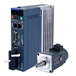
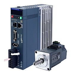
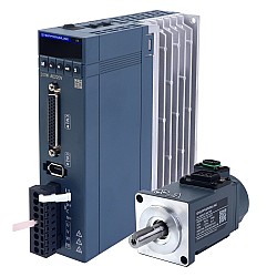
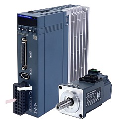
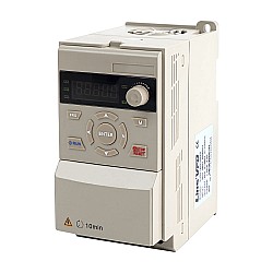
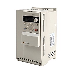
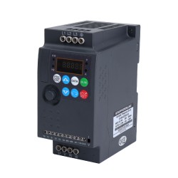
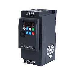
If you are a beginner who is just learning about electric motors, you may have heard the term "VFD" a lot. But what a VFD is and how it works, the types of VFD, the advantages and disadvantages of VFD, and the related applications of VFD are the basics of VFD you may not know very well, and this article is well suited for a beginner.
What is a VFD?
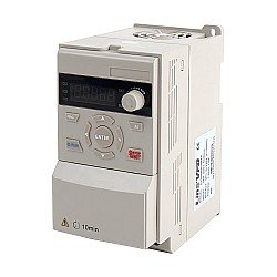
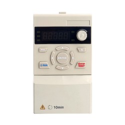
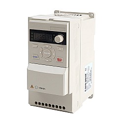
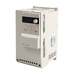
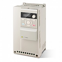
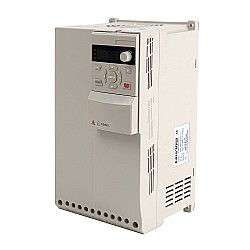
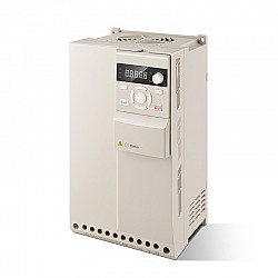
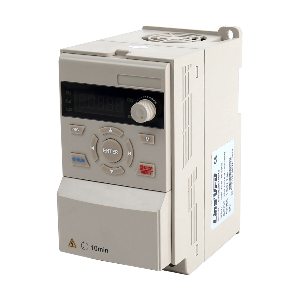
A VFD or variable frequency drive is a type of electronic device used to control an AC induction or synchronous motor by varying the frequency and voltage of its power supply to drive the motor. Despite the fact that the drive controls the frequency and voltage supplied to the motor, we usually refer to it as speed control because the result is an adjustment of the motor's speed. Other names for VFD are: adjustable speed drive, adjustable frequency drive, variable-voltage/variable frequency drive, AC drive, Microdrive, Inverter, variable speed drive.
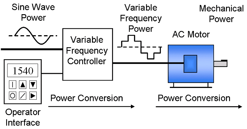
A variable frequency drive is a device used in a drive system consisting of three main subsystems: the AC motor, main drive controller assembly, and drive/operator interface.
- An AC motor, usually a three-phase induction motor, but sometimes a single-phase or synchronous motor.
- A main drive controller, using a solid-state power electronic conversion system, consisting of three different subsystems: a rectifier bridge converter, a DC link and an inverter.
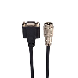
- A monitoring and control interface, which provides the operator or PLC with the means to start and stop the motor, adjust speed, change direction, etc. The interface also offers information about the operation of the motor, the health of the drive, etc. Communication with a PLC can be accomplished through a number of serial communication protocols or through old-fashioned relay inputs and outputs combined with 4-20mA or 0-10V analog signals.
How does a VFD work?
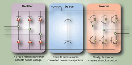
In order to understand how a VFD works, next I will explain the four main parts of a VFD: rectifier, DC bus/DC link, inverter, and control circuit.
1. Rectifier
It converts the AC input from the main power supply to DC. This part can be unidirectional or bidirectional depending on the application used, such as the four quadrant operation of a motor. It utilizes diodes, thyristors, transistors and other electronic switching devices.
2. DC bus/DC link
The DC link stores the power converted by the rectifier, removing ripples from the rectifier's pulsating DC output and providing a smooth DC voltage. It consists mainly of capacitors to filter the ripples from the pulsating DC and store it. It may also include an inductor, which depends on the type of ripples.
3. Inverter
This part consists of electronic switches, such as transistors, thyristors, IGBTs, etc. It receives a steady DC current from the DC link and converts it to an AC current with adjustable frequency, which is then delivered to the motor. It employs modulation techniques such as pulse width modulation to vary the output frequency to control the speed of the induction motor.
4. Control Circuit
It consists of a microprocessor unit. It transmits signals to the rectifier, DC bus and inverter, and it also receives signals from these parts. It uses the signals to switch on and off the semiconductor devices of the inverter, provides various control signals to operate the inverter, and monitors the operating status of the inverter to provide protection functions.
Types of VFD
There are two main types of variable frequency drives on the market: mechanical and electrical.
Types of mechanical VFDs
1. Variable pitch drive
This VFD is a belt and pulley drive, where the pitch diameter of one or both pulleys can be adjusted according to specific requirements. This mechanism imposes a multiple ratio, which ultimately results in a variable output speed.
2. Traction drive
In this VFD, the diameter of the contact path belonging to the two mating metal rollers is adjustable, giving a multiple ratio and thus a variable output speed.
3. Hydrostatic drive
This VFD consists of a positive displacement hydraulic pump and motor. The volume of fluid output from the pump is varied using valves or by changing the displacement.
4. Hydraulic hydro viscous drive
In this VFD, a number of discs on the input shaft are pressed against a corresponding number of discs on the output shaft. Between these discs is a thin film of oil. By changing the pressure of the squeezed discs, the torque transmission can be changed, thus achieving variable speed operation.
5. Hydraulic hydrodynamic drive or fluid coupling
In this VFD, the two impellers are coupled together using hydraulic fluid. By changing the volume of the fluid, the degree of coupling from primary to output can be varied, resulting in variable speeds. It is the most commonly used mechanical VFD in industry.
Types of Electric Drives
Eddy-current Coupling
This VFD exists between a fixed speed motor and the application driven by the motor. It consists of a fixed speed rotor and a variable speed rotor with a small air gap in between. An excitation winding is provided on one of the rotors to create a magnetic field that couples the rotors together and determines the transmitted torque.
DC Drives
A DC drive involves a DC converter converting the supplied AC power into a variable magnitude DC voltage and supplying it to the armature winding of a DC motor. DC drives typically make use of thyristor technology and can be used in all of the above non-hazardous area applications.
AC Drives
There are three main types of VFDs, all of which convert AC input to DC and then change the DC to variable AC output with the help of an inverter.
- Direct conversion: This type includes cyclo-converters and other matrix topologies where the input AC is converted to variable AC in one stage. These VFDs are most commonly cyclo-converters that control synchronous motors with brush or brushless excitation. These VFDs are used in applications where the motor speed is low and the torque requirement is high.
- Current Source: It behaves like a constant current generator, producing an almost square wave of current. The current source VFD for controlling synchronous motors is also referred to as a load commutated inverter (LCI) VFD and typically uses thyristor technology. Its response is much slower due to the inductive source, so it is only suitable for fan and pump type loads.
- Voltage source: In a VSI drive, the DC output of a diode bridge converter stores energy in a capacitor bus to supply a stiff voltage input to the inverter. VSI drives work with both induction and synchronous motors. Voltage source inverters are the only choice for drives above a certain power rating. The vast majority of drives are of the VSI type with PWM voltage output. Currently the most common electrical VFDs used in industry are AC inverters that use the voltage source inverter (VSI) type.


Advantages of VFD
Energy & Energy cost savings
Motor systems consume more than 65% of the electricity consumed in industry today. Optimizing motor control systems using VFDs can lead to significant reductions in equipment energy consumption. Especially in pumps, fans, and compressors, VFDs can achieve significant energy cost savings.
Efficient and smooth control
By controlling the motor at the most efficient speed, errors are reduced. VFD enables smoother belt and conveyor action, which eliminates jitter at start-up and reduces thermal and mechanical stress on the motor and belt drive.
High power factor
The power factor correction circuitry built into the DC link of the VFD reduces the need for additional power factor correction equipment. This eliminates the need for additional expensive capacitor banks.
A typical AC motor may have a full load power factor between 0.7 and 0.8. As the motor load decreases, the power factor becomes lower. Especially in no-load applications, induction motors have a very low power factor. Low power factor causes low power utilization due to high reactive power losses.
Extend equipment life and reduce maintenance
VFD provides better protection for your motor against problems such as electrical overload, phase protection, under voltage, overvoltage, etc. because of the optimized control of motor frequency and voltage. Using a VFD to start a load protects the motor or driven load from the " instant shock" of across-the-line starting. Smooth starting eliminates a lot of belt, gear and bearing wear. An added benefit is the reduction or elimination of water hammer through smooth acceleration and deceleration cycles. This can help extend the life of the equipment and minimize downtime due to maintenance.
Disadvantages of VFD
- The initial cost of a VFD is typically higher than other variable speed control devices.
- The user interface of a VFD is still more complex than that of a cross-line starter.
- Induced Harmonics: A variable speed drive is a non-linear load that induces harmonics to the power line. VFDs, especially high horsepower drives, require harmonic filters on their lines so that this distortion is not transmitted to potentially sensitive electrical equipment.
Applications of VFD
In fact, there is no application for which an AC motor is not suitable for VFD operation. If the VFD offers many benefits for a specific application and the cost is reasonable, then the VFD application is acceptable.
The use of VFDs in HVAC fan and pump applications can save energy and energy costs, and in industrial applications can improve motor torque and speed control, as well as improve motor protection.


-3-200x160w.jpg)


-1-3-250x250.jpg)
